Rotor Test Rig
The rotor test rig can be used to observe the structure of rolling bearing. It can also be configured sensors for measuring mechanical parameters such as vibration, speed, noise and displacement. The transient process of speed up and down of rotating machinery and the vibration state of steady-state operation conditions can be simulated. According to the date acquired by the machine, we can analyze the fault characteristics of a variety of common rotating machinery faults.
The rotor test rig in our lab mainly consists of the following parts:
1-base, 2- spindle, 3- spindle support, 4-motor, 5- speed measuring gear, 6- motor bracket, 7- bracket for eddy current sensor, 8- speed sensor bracket, 9-reducer, 10- motor governor, 11- bracket for friction screw.
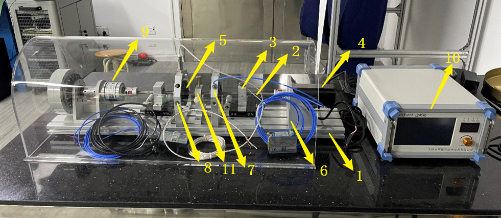
Fig.1 The Structure of Rotor Test Rig
The main technical indexes are as follows:
(1) Model: WUXI HOUDE HZXT-008
(2) Adjustable speed range: 0~3000RPM
(3) Spindle length: 500mm
(4) Spindle diameter: 10mm
Firstly, the sensor needs to be installed on the experimental platform. And the signal line of the sensor needs to be connected to the corresponding signal receiver. Then the corresponding software can be used for data acquisition.
